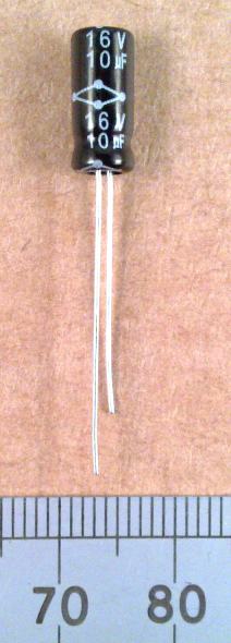

The negative lead is marked on the case with a white stripe and a negative '-' symbol. That is also the shorter wire in most instances. 16V is the maximum working D.C. voltage that is allowed on the capacitor. In our 9 Volt battery circuit, a 10V capacitor would do. If you went up to 12 Volts on the battery, you'd be in trouble if the capacitor was connected directly across the supply rail. You can use a capacitor with a higher voltage rating where a lower voltage is specified.
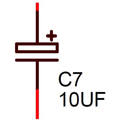
Standard electrolytic capacitors must be fitted the right way round in the circuit. UF, (generally used in electronic CAD schematic diagrams) or uF, (most often used in text) or most correctly μF, (using the Greek letter lower case mu "μ") stands for microfarads. On capacitors made back when dinosaurs still roamed the Earth, and on equally ancient schematics, you may see the bad practice of writing this as mF or MF.
In the circuit, C7 is used to set the automatic gain control (AGC) time constant. In conjunction with the track resistance of VR1, it filters the audio signal in such a way that the D.C. voltage drops in line with sound level peaks. This reduces the transistor bias currents to the radio frequency sections, they have a harder time driving the signal into the load of the next stage, and that reduces the overall RF circuit gain.