The
Choccy Block Simple Ring Mod: A
No-Soldering Diode and Transformer Ring Modulator Kit
This kit is
currently available only as the main
components, the four diodes and the
transformers. Finding consistent jack
leads to accurately match the pictures has
proved to be very troublesome, and you can
easily find them yourself anyway.
The online marketplace buying options can be
found here: HJW
Electronics Online Marketplace Buying
Options

Picture of the Basic Ring Mod Schematic, Click to enlarge.

This is a very simple ring modulator circuit which will allow
you to make interesting analogue sound effects using two audio
sources and some kind of amplifier or recording device.
Almost everyone has access to a couple of mp3 players and some
powered computer speakers nowadays, so this is quite an easy way
to go about it. One very familiar use for this old style
of ring mod is that which produces the "Dalek" voice. I
will concentrate on that application in the text, but there are
other effects you can produce which I'll discuss later.
Bill Of Materials
Electronic Parts Included in the Kit
Qty
Refs
Type
Value
2
L1,L2
Transformer LT44
4 D1,D2,D3,D4
Schottky Diode BAT48
3
J1,J2,J3 3.5mm Stereo Jack Leads
Miscellaneous
1
10-way 3A Terminal Strip
20mm
Plastic Sleeve
Link
to PDF of Simple Ring Modulator Schematic
Link
to PDF of Simple Ring Mod Bill Of Materials
Pre-Requisites
Tools
I supply a kit of all the electronic parts in the list above, or
you can buy your own. I've assumed that you have a small
screwdriver for the terminal screws, some small wire cutters for
trimming the component leads and some means of stripping the
insulation from the wire. A craft knife is good for
that. It is best to mount up the circuit in an enclosure or
nail it down to some wood when it is all working, and the holes in
the terminal strips make that easy to do.
What do you need to know before
you start?
This is a nice simple circuit which you can make pretty much just
by looking at the final picture. The components list has
links to photographs of the components. I've included a full
electronic explanation later on. If that doesn't make any
sense, don't let it put you off just building the circuit.
How To Build It: Follow The Pictures and Schematic
Diagram
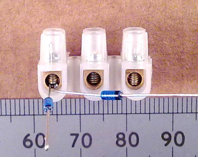
Cut Up the Terminal Strip and Assemble the Diodes
Using a craft knife or scissors, cut the terminal strip into two
pieces of two terminals and two pieces of three terminals.
The four diodes can then be assembled the correct way around by
cutting the leads to about the right length and trapping the
ends under the screws in the terminal blocks as shown. I
fold the leads of the diodes back a bit at the end to make them
easier to trap properly under the terminal screws. Don't
tighten the screws too much at this stage as you may want to
re-adjust the assembly.

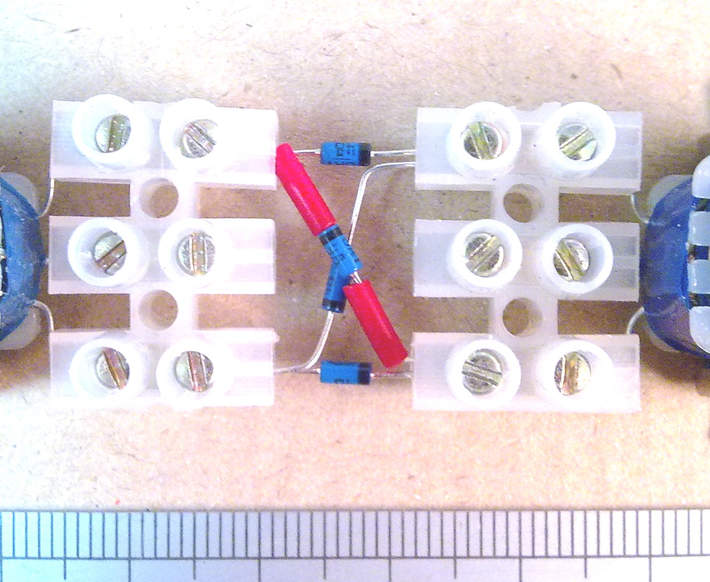
There is a small length of PVC insulation provided which can be
put on the leads of one of the diagonally mounted diodes. This
avoids it shorting against the other one. You should now
have something that looks like this:
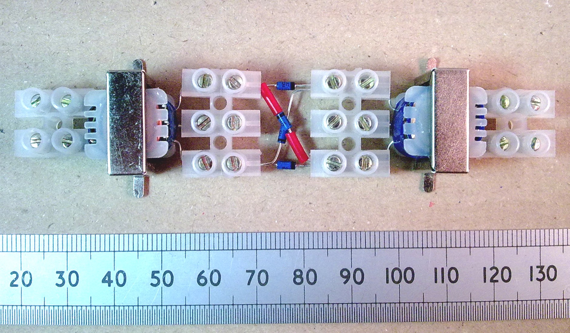
Connect Up The Transformers
Next connect the two transformers in a similar way. The
transformer sides with the three wires go into the three-way
terminal blocks with the diodes, and the side with the two wires
connects into another two-way block.
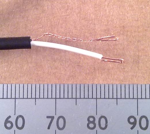
Make the final connections to the
Input - Output Plugs
Next, strip the wires on the jack plug leads by carefully
scoring round the outer PVC and then the inner core and baring
the copper wire as shown. Twist the bare wires and fold
them back at the ends to make them easier to trap properly under
the screws. Then connect them up as shown, one to the two
terminals on the left, another to the two terminals on the
right, and the final lead to the two centre terminals in the
middle. I have used the white cored wire and this
corresponds to the left channel.



Thatís It, but Check and Secure
This is a pretty simple project and if you're sure everything is
in the right place, you can screw down the terminals a bit
tighter and make sure that everything is secure.
Starting Up and
Initial Testing

I've labelled the three plugs A,B
and C. C is the output from this circuit and that needs to
plug into some computer speakers, or a line input to an
amplifier with some speakers or headphones. I'm going to
call C just the "output."
A is the input which has the voice signal fed into it.
This needs to connect to the headphone output or line output of
some mp3 player which has the voice signal to be processed on
it. If you have a portable recording device with a
microphone, you may well find that the signal from the
microphone is amplified and played out of the headphones while
recording. In that case you can use that as a microphone
amplifier and use the system live, speaking into the
microphone. I'm going to call A the "voice input."
B is the input which needs to be connected to another mp3 player
or similar device which is going to play back a 30Hz sine wave
signal. There are links to mp3 and wav versions of 30Hz
tones shown below. If you have an electronic signal
generator you can use that instead, and that will allow you to
change the frequency of the tone in real-time. I'm going
to call B the the "tone input."
Be careful with the volume setting on the output amplifier at
first and adjust it upwards only when everything seems to be
working right. Set the tone input and voice input to
midway and when everything is set to playback you should hear
the processed voice coming out of the speakers. If you've
set up a live microphone input you might get feedback if the
speakers are set too loud. Using a live mic is the most
amusing.
If you've made this especially for Dalek impersonations, bear in
mind that the gold coloured ones who are in charge have that
deep gravelly voice, while the red footsoldiers tend to have the
somewhat higher voices and can be easily panicked if used as a
hatstand or when certain people are mentioned. This
circuit is very similar to the original device used in the
1960's, so having gone to the trouble of building up the
hardware you can also claim some level of historic authenticity.
Picture of the sound sources
and 'amplifier' that I used for the demo:
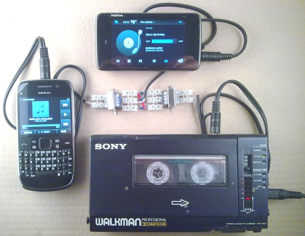
In the picture, the Nokia E6 is used to play the voice signal,
the N900 is used to play the 30Hz tone signal and the output
from the ring mod is plugged into the line input on the
venerable Sony WMD6C pro Walkman. I'm listening on the
headphone output of the Walkman as it records. The Nokias
conform strictly to a slightly ridiculous EU limit on headphone
output level, so they drive the circuit at a quite low
level. Here are the relevant audio files:
MP3 -3dB 30Hz Tone on Left and Right, 10 minutes, 44.1k sample
rate
WAV -3dB
30Hz Tone on Left and Right, 10 seconds, 44.1k sample rate
MP3:
A voice demonstration before processing
MP3:
A voice demonstration after ring modulation
If I'd wanted to use a microphone live, I would have had
to find something else to use as the output amplifier and could
have used a microphone with the Walkman in record mode to
provide a voice signal.
Other
Things to Do
Left and Right
You might have noticed that we've stuck to using just the left
channel of two separate audio sources. This was just to
make handling the audio files easier. There's nothing to
stop you putting the tone and voice signals into one stereo file
if you know how to do that. I will leave the details to
the computer experts, but it's easy enough with some audio
editing software.
Higher Tone
Frequencies
You can turn up the tone frequency if you're using a signal
generator to create interesting frequency shifting effects that
way. What happens is that two versions of the voice signal
are created. One is shifted up in frequency, and the other
is shifted down. The down shifted voice also reflects
through zero Hz and is frequency inverted as the tone signal
increases in frequency. Feedback from the speakers can get
very interesting if you have the live microphone set-up
too. If you have a long corridor and some long speaker
cables, feedback from speakers to mic with different tone
frequencies can get you into high-quality interesting Quatermass
sound-effect territory. Similarly you could use a short
tape or digital delay with this in the feedback path. Even
if you use a digital delay, using an analogue processing stage
like this introduces various forms of noise and distortion which
can turn a boring digital effect into something much more
interesting.
Reduced Tone
Level
The operation of the diodes at normal drive levels has them
either turned on or off most of the time. This introduces
more harmonics into the voice signal. If you are trying to
produce the frequency shifting effects already mentioned, these
can be heard more clearly by reducing the tone level to a point
where the diodes are operating more linearly.
Squaring or
Frequency Doubler Operation
To Follow. Basically, you feed the same audio signal into
the audio and carrier inputs resulting in an interesting
frequency doubling effect at the output.
More Detailed Electronic
Discussion
(More To Follow.)
Double balanced modulators like this were traditionally used in
older radio circuits using radio frequency transformers to
produce suppressed carrier AM signals. If you look up
circuits like that and compare it to this application, it can
appear a bit confusing as the RF 'carrier' input would be
connected our 'voice' input and the 'voice' input would be going
into our 'tone' input.
You might have heard that it's a good idea to match the diodes
so that they all have about the same Vf, the forward voltage
drop, and that a low forward voltage drop is a good thing.
All the BAT48s that I've seen so far have been very closely
matched straight out of the bag, and have a low Vf at the
currents that we are using them at. You can use other
signal diodes if you want, and higher Vf non-Schottky silicon
types like 1N4148 will probably sound a bit different at some
drive levels.
FAQs
Q: I can't hear anything when I play back the 30Hz tone
mp3.
A: 30Hz is generally too low to hear. Don't play it
back too loud in media player or it might damage your speakers.
Q: I would like a circuit that does all this on battery
power with a microphone and speaker on one circuit board.
Is there one?
A: There is, but it's not in kit form yet. I'll be
publishing that at a future date. Meanwhile you can see
the circuit here: Portable
Dalek Voice Ring Modulator Circuit
Q: Why not use the red LT700 type audio output transformers like
many others do?
A: Because they really are intended for low impedance
loudspeaker matching into 3.2 Ohms. That's a bit tough to
drive on the voice input side and produces quite a low signal
voltage on the output.
Q: Can't I do this on the computer much more easily?
A: Yes, but it's not as interesting and it never sounds
quite the same due to various secondary properties of the real
circuit.
Should you have any problems or questions, my main
email address is shown below. This address
has been the same since 1997 and unless I'm on
holiday beyond mobile coverage, it is checked
daily including the spam folder.

Navigate
Up
Recent Edit History
22-JUN-2025: Changed om buying options link to
local summary page.
22-DEC-2025: self canonicalised, direct refs


