The
HJW Electronics Choccy Block Flashing Lamp Flip-Flop: A
No Soldering Alternate Flashing Light Kit
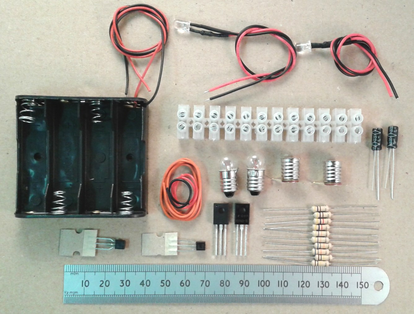
A complete kit of all the
electronic parts shown is available here: HJW
Electronics Sales Information


Introduction
This
is a light flashing circuit which alternately flashes two LEDs
or two lamps. It is based on a circuit called a flip-flop
or astable multivibrator and it has two additional transistors
to allow you to flash
two sets of several LEDs or lamps wired in parallel.
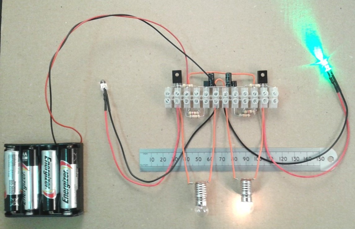
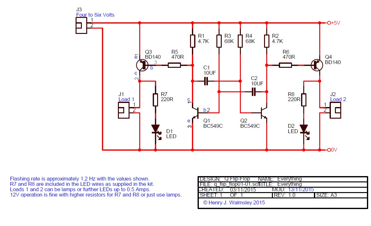
Picture of the flashing light flip-flop schematic diagram.
Click on any picture to enlarge.
Flashing Light Flip-Flop 1 Bill Of Materials
Electronic Parts Included in the Kit. Click on the links
for details and pictures.
Qty
Refs
Type
Value
2 R1,R2
Resistor
4.7K 0.5W
2 R3,R4
Resistor
68K 0.5W, alt values 47K and 100K
2 R5,R6
Resistor
470R 0.5W
2 C1,C2
Capacitor
10uF NP
2 Q1,Q2
Transistor
BC549C
2 Q3,Q4
Transistor
BD140-16
Miscellaneous
1
12-way
3A Terminal Strip
1
4
X AA Battery Holder
2
2
X M.E.S. lampholder
2
2
X 6V 0.1A lamps
1
D1
red wired LED with resistor
1
D2
green wired LED with resistor
0.5
100mm
black single core wire
1
100mm
red single core wire
4
100mm
orange single core wire
Link
to PDF of Flashing Lamp Flip-Flop Schematic
Link
to PDF of Flashing Lamp Bill Of Materials
Pre-Requisites
Tools
I supply a kit of all the electronic parts in the list above, or
you can buy your own. I've assumed that you have a small
screwdriver for the terminal screws, four
AA batteries, some small pliers, some small wire cutters
for trimming the component leads and some means of stripping the
insulation from the wire. A craft knife is good for
that. It is best to mount up the circuit in an enclosure or
nail it down to some wood when it is all working, and the holes in
the terminal strips make that easy to do.
Precautions
Use normal sense and don't short circuit the batteries, i.e. take
care not to connect the red wire directly to the black wire.
Modern alkaline batteries produce a fair amount of current and the
wires and batteries may start to get warm. Do not use
rechargeable batteries. Rechargeable batteries can produce
large currents if accidentally short-circuited.
What do you need to know before
you start?
This is a fairly simple circuit which you can make pretty much
just by looking at the pictures. The components list has
links to photographs of the components and some further
information. I've included a full electronic explanation
later on. If that doesn't make any sense, don't let it put
you off just building the circuit.
How To Build It: Follow The Pictures and Schematic
Diagram in Three Stages
There are three main stages to
building up the circuit, and these were chosen so that you can
see where the earlier components go in the pictures before they
are partially covered up by the later stages.
Stage 1, Fit the Transistors, Wires links and Resistors
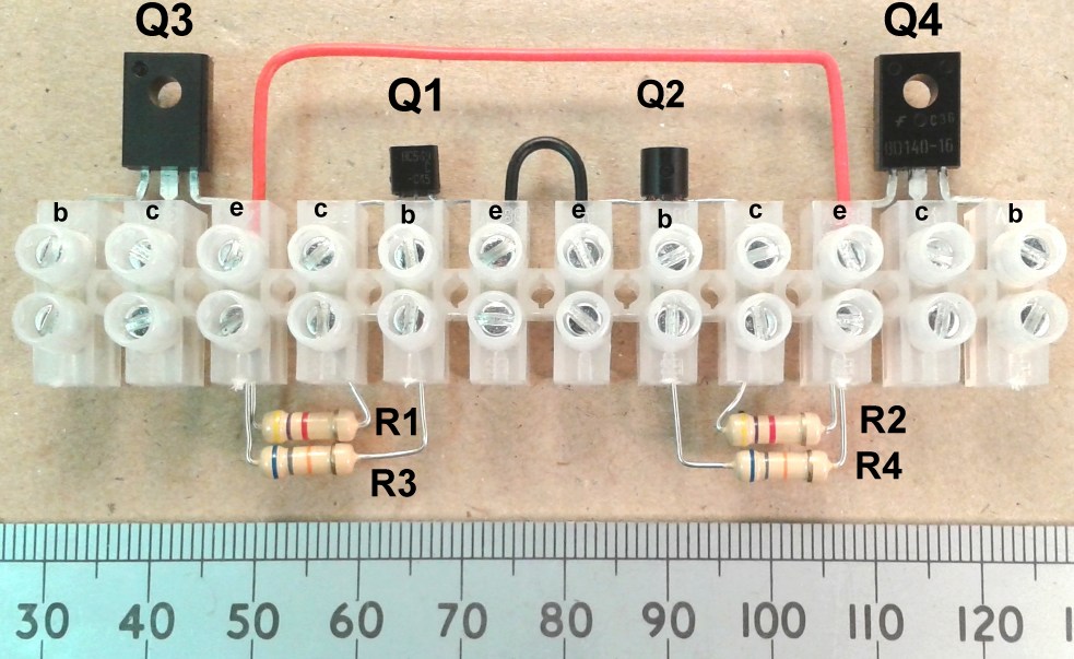
Bend the leads as shown and assemble
Q1,Q2,Q3,Q4,R1,R2,R3,R4. Strip about 5mm of insulation
from the the black wire link and the red wire link and assemble
them as shown. Don't tighten the screws too much at this
stage as you may want to re-adjust the assembly. It's best
if you can get the leads in the right places so that they go
right under the screws and don't get stuck up the sides where
they may be loose later on. The following pictures show
some more angles and the leads going right under the
screws. Note that the transistors are fitted the opposite
way around on each side of the circuit. Q1 and Q4 are
fitted writing-side up. The resistors can be fitted either
way round but it will make checking easier if you put them with
the coloured bands facing the same way as in the pictures.


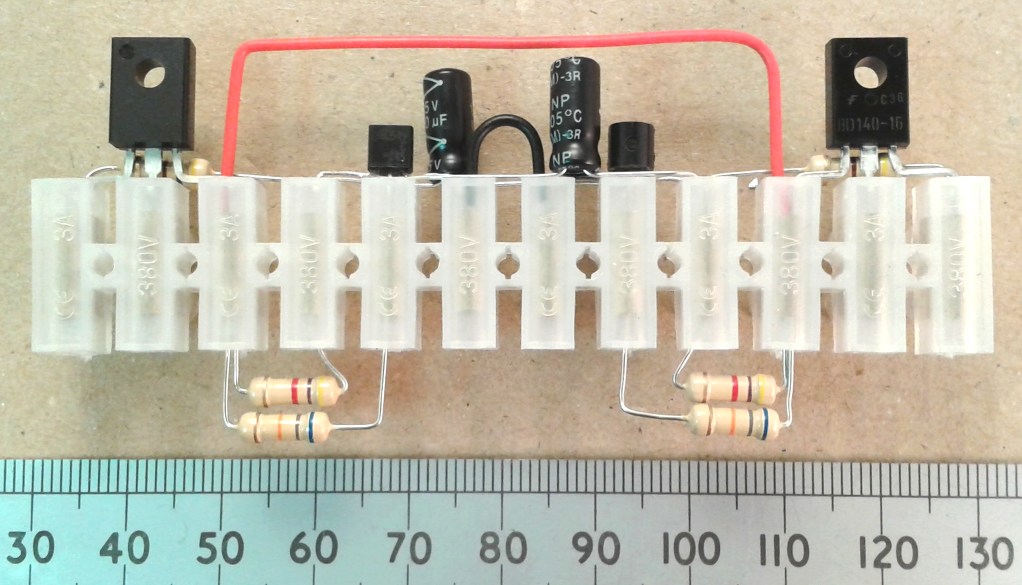
Stage 2, Fit the Capacitors and
Resistors

Now fit C1,C2 the two 10uF electrolytic capacitors and R5,R6
resistors. The capacitors bridge several connections so
you need to bend the wires so that they don't touch any
others. These are non-polar capacitors so they can connect
either way round. The marks C1x and C1y in the picture
show where the wires of C1 go in.


Stage 3, Connect the LEDs and Battery
Holder

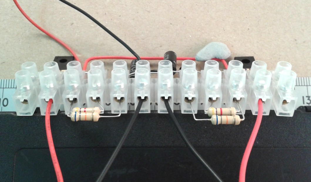
Strip back some of the insulation from the LED and battery
holder wires and fit them in as shown.



Thatís It, but Check and Secure
Have a final check around comparing against the pictures and
make sure that the wires are secure. You can now fit four
AA batteries with the negative ends towards the spring contacts
and the LEDs should immediately start to flash alternately, a
little faster than once per second.
Filament Bulbs and More LEDs
If the LEDs are working you can
connect the two filament bulbs if needed. The single core
orange wire should be put through the hole in the contacts on
the holders and wound tightly around and crimped down with
pliers so that it forms a tight bond which doesn't wobble.
The bulbs provided are 6V 0.1A but the transistors can cope with
up to 0.5 Amps. More LEDs can be added noting that each
one needs a resistor in series. For 6V operation of
standard 20mA LEDs that will be a 220 Ohm resistor.
The Completed Flip-Flop in Operation, YouTube Video


Changing the
Flashing Rate or Duty Cycle
Using 68K for R3 and R4 and 10uF capacitors results in a
flashing rate of slightly more than once per second. The
flashing rate varies in inverse proportion to the resistance, so
you can increase the flashing rate by changing them to 47K or
decrease it by using the 100K resistors. Using a lower
value resistor on one side only will change the duty cycle and
give a shorter flash on that side.
12V
Operation
Operation on 12 Volts is possible
from small batteries or a current limited supply if you increase
the resistor in your LEDs to 560 Ohms or change the bulbs to 12V
ones. The maximum current is 0.5A so check the rating on
the bulbs. I don't recommend using 12V supplies
from a car or car battery as they are very high current and
accidentally shorting them can cause fires.
How It Works While Running
Forget about Q3 and Q4 for now. They have only a small
effect on Q1 and Q2 and can be considered separately from the
switching action. Looking at the oscilloscope pictures
further down the page might help here.
Imagine that there are no capacitors C1 or C2 connected.
Transistors Q1 and Q2 are high gain amplifiers. A small
current flowing through the base to the emitter will cause a
larger current to flow from the collector to the emitter.
Resistors R3 and R4 provide just such a small base current from
the positive rail. The base voltages are about 0.7V which
is what you normally see when some small current is passing
through them in the direction of the arrow on the transistor
symbol. If there were no capacitors C1 and C2, this is
just what you would see as two independent circuits with no
interconnections. The collector of Q1 would be at a low
voltage pulling current through R1, as would the collector of Q2
pulling current through R2. Imagine first that C2 has been
connected. For a short time it will pull a bit of current
out of Q1 base as it is effectively connected to ground by Q2s
collector before everything settles down again.
Now we require a leap of faith.
Imagine that the right hand side of C1 has somehow been charged
to minus 6V and connected to Q2 base. This turns Q2 off
completely, Q2 collector rises to 6V pulled up by R2, and
suddenly dumps charge through C2 into Q1 base, turning it on
even harder and causing a small voltage blip on Q1 base.
Meanwhile, that minus 6V on the right of C1, (Q2 base) is rising
all the time, charging up slowly through R4. When it
reaches the turn-on voltage of Q2, about 0.7V, Q2 collector
voltage drops quite rapidly pulling current out of Q1 base
turning it off, Q1 collector starts rising and dumps charge into
Q2 base making the collector turn on harder and creating that
blip of voltage on Q2 base. Because C2 was charged up to
6V on the right, and that end has now been pulled to zero volts,
the left side of it is now at minus 6V turning Q1 right
off. Meanwhile, R3 is now slowly charging up the left hand
side of C2 from that minus 6V ready to turn on Q1 base
again. As Q1 base starts to turn on, Q1 collector falls
rapidly pulling current out of Q2 base via C1 and ending up with
the right side of C1 at minus 6V. That's where we started
out and you can see that the cycle must continue.
As Q1 starts to turn on fairly gradually as the base voltage
climbs slowly from about 0.5V to 0.7V via the fairly weak
resistor R3, its high gain and the threshold voltage (Vbe)
around 0.7V is what causes a more rapid drop in Q1 collector
voltage turning Q2 off rapidly via C1, and the rising Q2
collector voltage on the other side reinforces the Q1 turn on
via C2. It's this positive feedback loop that causes the
transistors to switch, or flip, quite sharply once the threshold
has been passed. Hence the name.
Oscilloscope Pictures Of The Circuit in
Operation.
In order to get a clear trace on an analogue oscilloscope I
fitted 0.01uF capacitors so that the circuit was oscillating at
about 900Hz. The vertical range is 2V/division and the
horizontal is 0.2mS/division. Zero volts is marked by the
underlining in the CH1/CH2 text.
Q1 and Q2 Base Voltages
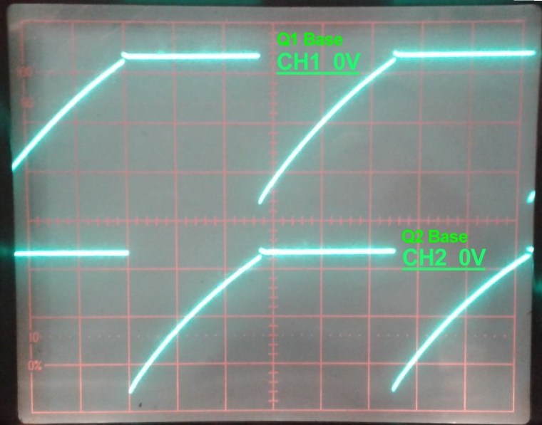
This shows that the base of the transistors and one side of the
capacitors really do spend a lot of their time rising from
almost six Volts below the zero volt rail while charging through
the timing resistor.
Q1 and Q2 Collector Voltages

You can see that the traces drop much faster as the transistors
pull down strongly when switched on, and rise more slowly as the
stray capacitances of the LEDs etc. charge up through R1 and R2
Q1 Base versus Q1 Collector Voltages
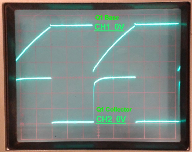
Q1 base versus Q2 Collector Voltages
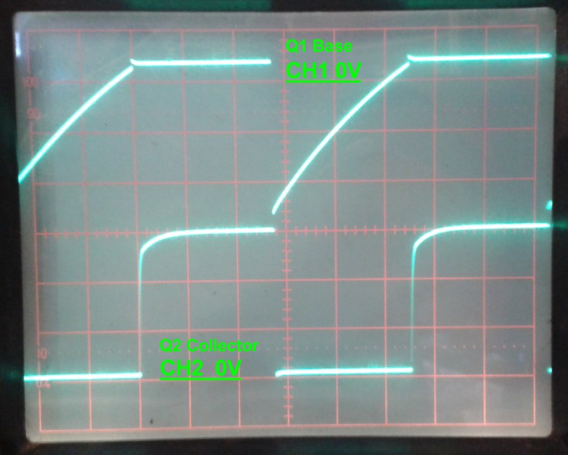
This last picture has the probes across one of the capacitors
and shows the place in time where the voltage across the
capacitor C1 gets reversed for a short period. That is
when the CH2 trace is still down near 0V but the CH1 trace has
risen significantly above 0V, just before Q1 starts to turn
on. The little jump and squiggle on the top trace at this
point is when Q2 turns off and the rising collector voltage
pushes positive charge from C2 into Q1 base to turn it on even
harder.
Q3 and Q4 Output Transistors.
Q3 and Q4 are used to isolate the low current switching action
of Q1 and Q2 from the effect of the main loads, the LEDs or the
lamps. Q3 and Q4 are PNP medium power transistors, unlike the
small signal NPN transistors used for Q1 and Q2. PNP
transistors are used so that it is the positive supply rail that
is turned on and off, with the current returning possibly via a
common ground wire. Also, some current is required to
drive through the bases of Q3 and Q4. If they were NPN,
that current would have to be supplied as a positive current
though R1 and R2 which would be fairly weak. Using a PNP
allows that negative current to be supplied by Q1 turning on
which is a much stronger source. When Q1 is turned off
there is no current through Q3 base as R1 and R5 are pulling the
voltage up toward the positive rail. When Q1 turns on,
current flows through Q3 base in the direction of the arrow on
the symbol, down through Q1, again, in the direction of the
arrow. This causes a large current to flow down from Q3
emitter to collector, through the LEDs or lamps. Q3
typically has a current gain of about 100 at 100mA collector
current, so the base needs a current drive of about 1mA.
Q1 can do this easily thanks to its own current gain of about
300, even though its own base is only driven by the 68K resistor
R3 (most of the time) giving about 70uA. R5 limits the
base current of Q3 to about 10mA. Because the output
transistors are either completely off or are turned on quite
strongly except when they're switching, they don't dissipate
much heat even running at 0.5A, which they only do for half the
time anyway. There is no need to attach them to any kind
of heatsink.
It's possible to put LEDs with series resistors or indeed low
current bulbs in the locations where R1 and R2 are. Then
you can just use two transistors. This has some
disadvantages. You need an equal load on each side.
If one of the bulbs breaks, the
circuit stops. If the bulb is too high
power rated, the small transistor won't pull the collector all
the way to ground. As discussed, that helps the circuit to
oscillate in a clean way. You can use bigger transistors,
but their lower gain means lower values for R3 and R4 which
means bigger capacitors.
How It Works While Starting
Up
Thinking about what happens when
the circuit is first starting up can make your brain
hurt. You can see that I had to employ
a leap of faith to get started in the description above, and
hopefully convinced you with the arguments about the transistor
gains and the reinforcing action of the cross-connected
capacitors during switching. It's possible to imagine
though, that when starting up, you could end up up with a draw
in the race to switch first where the circuit would be stuck in
some middle state. In practice small differences in the
values of the components and transistor gains makes one side
switch on first. Even if everything was perfectly matched,
tiny amounts of electrical noise would ensure that the balancing
act was pushed in one direction, then that side would win out
due to the positive feedback connection and the normal cycle
would start. People have written entire PhDs on the
subject of oscillator start-up.
More
Information
According to Wikipedia the
original flip-flop circuit was implemented with valves
early in the twentieth century, though I once made one with two
relays so I think it probably goes back even further. I
would not be surprised to see something equivalent in clockwork
or you could probably even devise a scheme which used flow of
water with alternate tipping buckets.
By using three or more switching transistors and it's possible
to make a running light effect, but I remember that getting it
to start up correctly was a bit more challenging. It's
probably time to switch to using digital gates at that stage of
complexity.
FAQs
Q: Doesn't this looks a bit like that circuit in the 1979
Ladybird Book, "Simple Electronics?"
A: Yes it does, though this is better. Even in 1979,
using AC128 germanium transistors was a bit a crime against
engineering.
Q: Can I drive relays instead of lamps?
A: Yes. You'll need ones with 5V coils or 12V coils
if you switch to a 12V supply. It's usual to put a reverse
biased diode across the relay coil to avoid the back emf
damaging the transistors when it turns off.
Q: It just won't work and I've tried everything.
What can I do?
A: My email address is shown below. If you can send
me well-focussed, good quality pictures of the main strip from
several angles and of the whole thing, I can usually get you
going.
Q: Why
bother with
the extra
driver
transistors?
Isn't it just
more parts and
more difficult
to build?
A: A
bit, but you
can drive real
things with
this circuit,
not just two
pathetic
LEDs.
Also, the
driver
transistors
isolate the
load from the
actual
flip-flop
circuit so
that, for
example,
mismatched
bulbs won't
cause the
circuit to
operate in a
lop-sided
manner.
Should you
have any
problems or
questions, my
main email
address is
shown
below.
This address
has been the
same since
1997 and
unless I'm on
holiday beyond
mobile
coverage, it
is checked
daily
including the
spam folder.

Navigate
Up
© Henry
J. Walmsley 2025.
Recent Edit History
22-NOV-2025: self canonicalised, direct refs


