Choccy
Block Crystal Set Radio Modifications, The Single
Transistor CBCSRK-1T
As a kid, I had a
hard time trying to make any published crystal sets work, and had
about zero success with single transistor radios either. So here's
one that does work, if you put all the bits in the right places. I
should add that in crystal set terms, this is a Massive Cheat.
When you've added a battery, it's no longer a crystal set.
On another page about a different design, I describe how
that radio doesn't use any, "funny electronic tricks." Well,
we're not in six transistor land now, so we're going for all the
tricks we can, to get the most loudness and sensitivity out of one
additional transistor and a single AA battery, using a few
additional components, and those already in the kit.
In the original CBCSRK-1 kit, there is a 12 section terminal
strip. Four of the terminals are unused. That
gives us an opportunity to add a transistor and a power
supply. We can "supercharge" our crystal
set. The intention is to keep the additional power requirements to
a minimum, in this case a single AA battery, or an alternative
1.5V power source.
Here's how to build the single transistor circuit. The electronic
schematic diagram is shown below, but you can just follow along
with the pictures to make up the parts. I've assumed that you've
already made the original crystal set, or at least read through
the instructions. You can click on the pictures to see enlarged
versions.
The Electronic Schematic Diagram
For the Single Transistor Modification
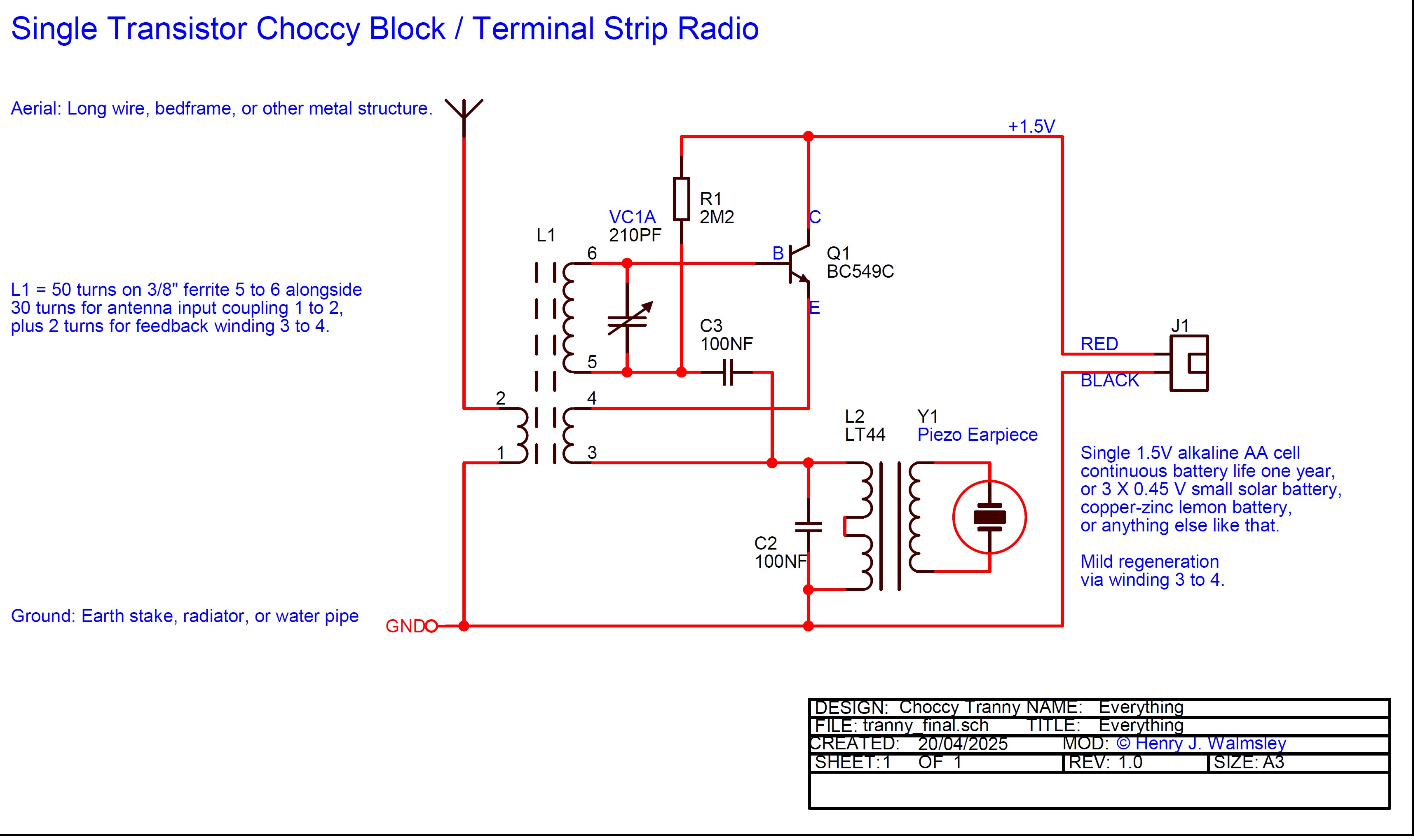
PDF Copy Of The Single Transistor
Terminal Strip Crystal Set Radio Modification
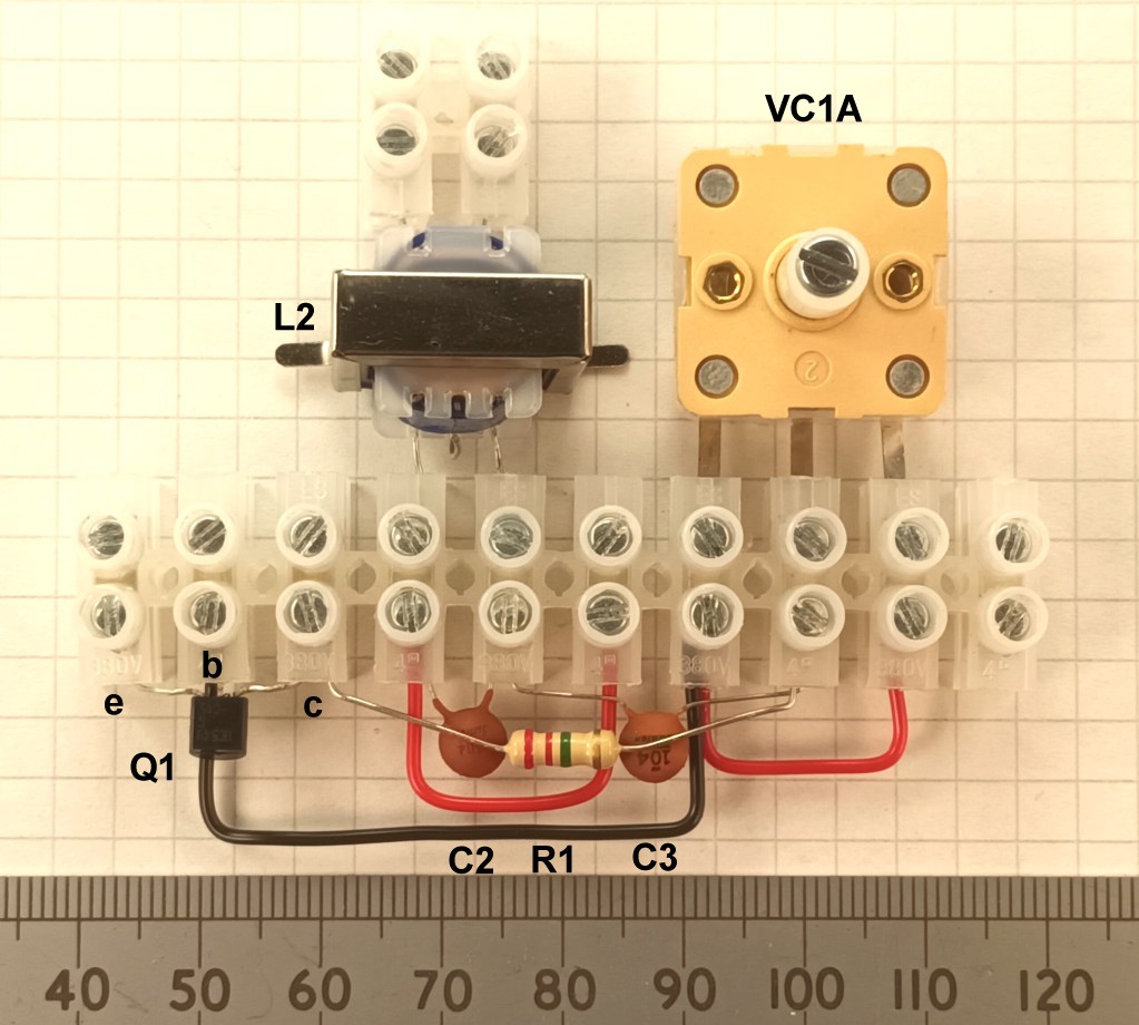
Assemble the
Components and Wire Links
First, disconnect everything that you've built for the crystal
set. Sorry, it's the best way. Then, build up the components as
shown. One important point to note is that you need to turn L2,
the audio transformer, the other way around so that the end with
the two wires is connected to the earpiece. The other
important thing to note is that Q1, the BC549C transistor must be
flat side up. I've used different coloured wires in the various
pictures to make the photographs as clear as possible, but use any
colour of wire provided in the kit.
The Components And Wire Links Connected Into The
Terminal Strip
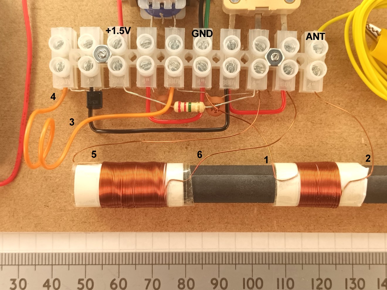
Connect in the Ferrite Rod Coils, Battery,
Aerial, and Earth Wires.
Then it's time to connect
up the ferrite coil L1, the battery holder J1, and the ground and
aerial wires. The numbers in the photograph match the pin numbers
on L1 in the schematic diagram. The two enameled copper wire
windings are the same ones as used in the original crystal
set. Pins 4 and 3 are the regeneration winding shown in
orange wire in the picture. This only needs to be positioned as
shown to provide a small amount of signal feedback into the
ferrite rod. It needs to be wound in the same rotational sense as
the main coil 5 and 6. In many situations with a decent
aerial, you may not need it at all, and you could just connect the
wire without taking it near L1. If you find that putting the
regeneration winding near L1 makes the output quieter, you need to
reverse the rotational direction of the winding. If the
regeneration winding is too close to the rod, the radio will make
a loud unpleasant squawking noise.
The Three L1
Coils Winding And Connection Detail
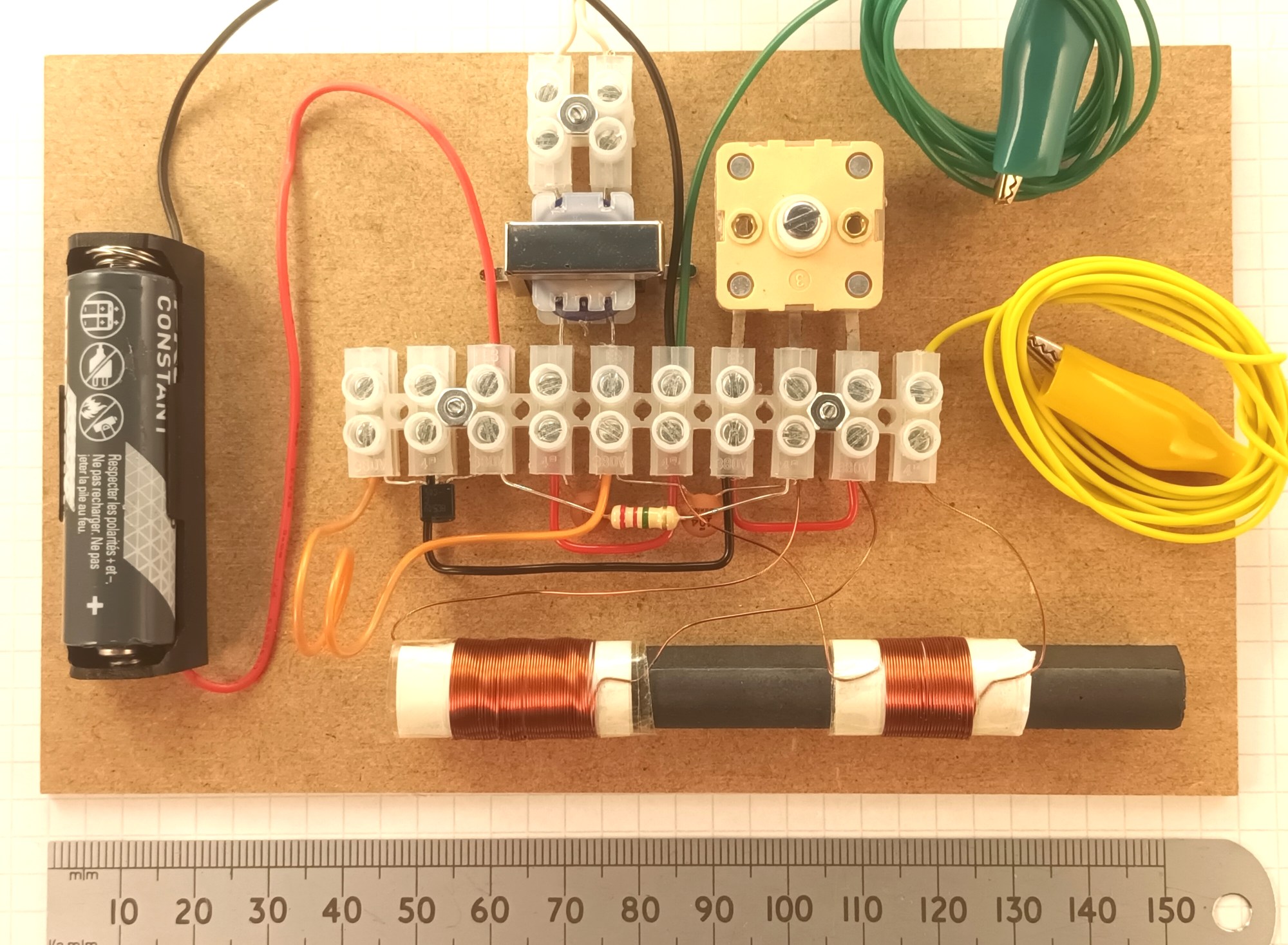
The Battery Holder, Aerial and Earth Wires
Connected.
Zoomed out slightly to
show the whole radio. The red and black wires for the battery
holder have to be connected the right way round, and you have to
fit the battery in the right way. The red wire is the positive
(+1.5V) wire.
Replace The Tuning Knob And Test
After that, you can put the tuning control
knob back on, and plug in a single AA alkaline battery. Do this
without the earphone in your ear in case it's too loud. Start with
the regeneration coil far away from the rod. Connect up the
crocodile clips to an aerial and earth connection of some kind.
This does not need to be anything like as good as with the purist
crystal set kit. Turning the tuning knob should bring in the main
stations that you might hear on a normal AM radio. To try for
maximum sensitivity, carefully edge the regen winding closer to
L1. You can disconnect the battery after use, but the radio uses
such a small amount of current that it should last for more than a
year.
The Completed Single Transistor Radio Kit
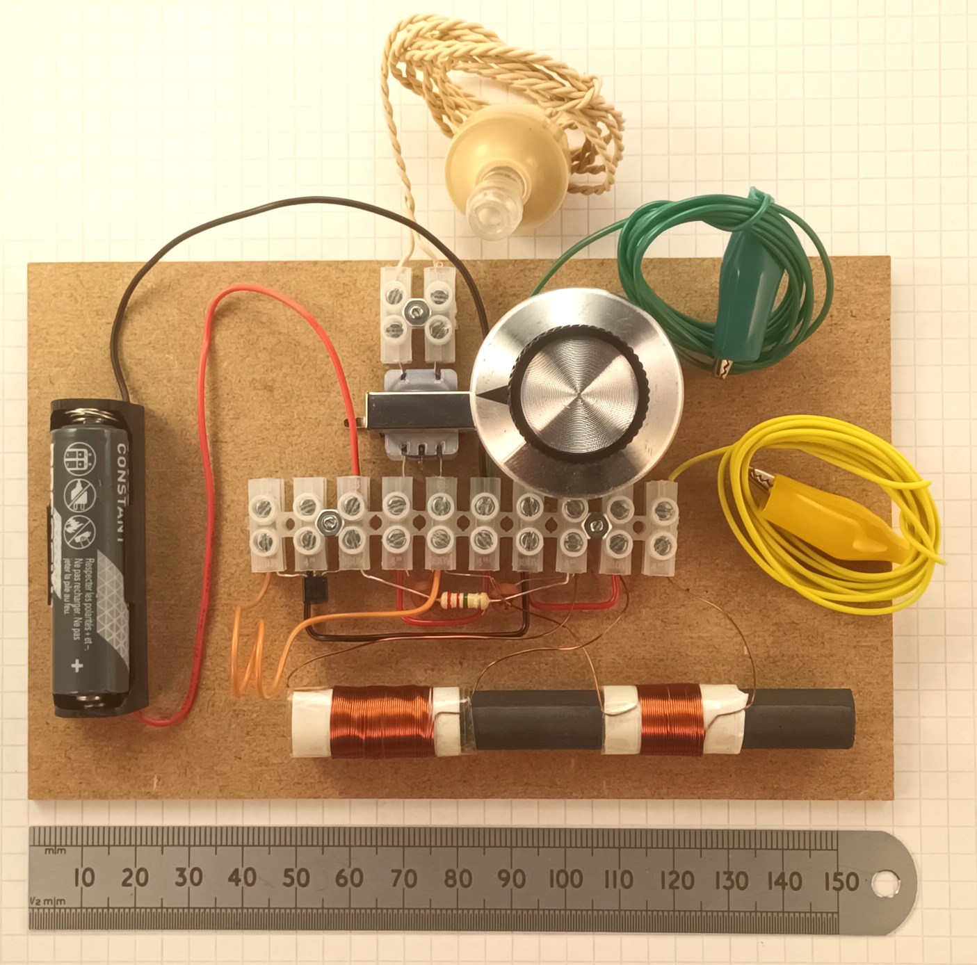
Is it any good? Yes. If you've been unable to get
CBCSRK-1 to work due to being in a valley, or a flat where you
can't launch much aerial wire, then I hope that CBCSRK-1T can get
you going. It will get both more stations where available, and
greater loudness. In MAY-2025 in Southampton, I get good reception
of BBC Five Live and Talk Sport, both from Brookman's Park in
Hertfordshire. That was using a central heating radiator for the
earth and a bit of wire leading up into the attic for the aerial.
Radio Wales is still going strong on 882 kHz over in the West. If
you're within 40 miles of Orford Ness, you should be able to hear
Radio Caroline radiating on 648 kHz. As with the crystal set,
moving the main coil further onto the rod will allow you to tune
lower frequencies and vice-versa. If you're in the USA where
transmitter power output tends to be greater, and AM still has
more popularity to cover the vast distances in some regions, you
should have success too.
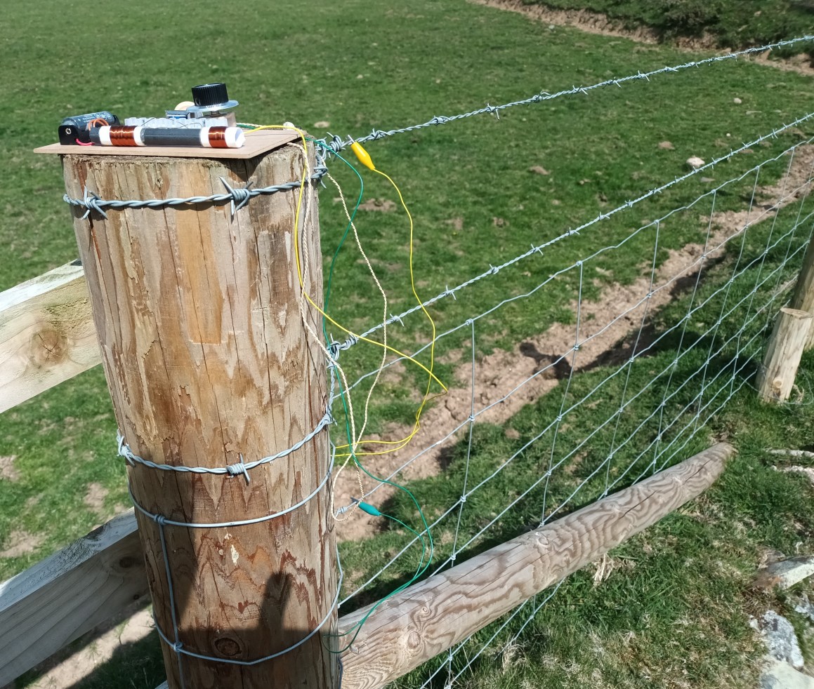
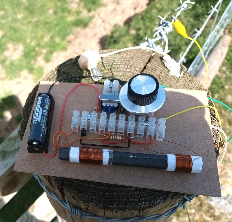
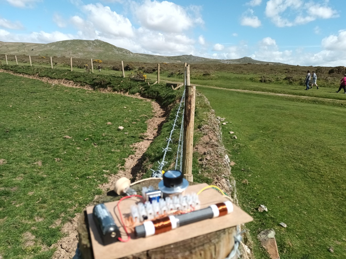
Depending
on your aerial, you might find that the tuning is rather broad
and that stations overlap. You can slide the aerial coil L1 pins
1 and 2 further away from the main coil to counter this. I found
this when testing on a farm fence in Dartmoor where the upper
wire and lower mesh of the fence were quite close together.
Another way to fix this is to try fewer turns on the aerial
coupling coil, anything down to 10 turns.
Some Radio
Testing On Dartmoor
How it works, The Simple Version.
Simple looking circuits rarely have simple explanations.
The aerial wire 2, to ground 1, induces radio signal into the
ferrite rod system L1.
The high Q winding on L1 pins 5 and 6 resonates with VC1A to tune
your station.
Transistor Q1 amplifies the radio signal from pin 6 of L1 and it
appears at Q1 emitter.
The radio signal gets fed back a bit to the antenna coil L1,
through regeneration coil connections 4 and 3. This boosts
the radio signal again via positive feedback.
The action of Q1 working only in the direction of the arrow acts
like an active diode, so after the regen coil, you get the
demodulated audio signal across C2 and L2 primary.
The audio signal gets fed back via C3 to be strengthened in
current by transistor Q1 through L1 pins 5 and 6. L1 doesn't care
about audio; It lets it straight through while still doing the
business of radio tuning. This provides reflex action or
bootstrapping for the audio signal.
Three active processes are occurring at once. You might
say that we're using one transistor three times.
More Modifications And Thoughts
I've shown this version of the kit bolted onto a piece of scrap
hardboard about 3mm thick. I heartily recommend this, and though I
don't provide the hardboard, I do provide the bolts. You might go
for the old cassette case option shown in the original kit, use
some stiff cardboard, or see what scrap bits are available for
free outside the local hardware store.
The 0.2mA current consumption from the 1.5V AA battery is very
low, so this is a great radio to run from a small solar battery or
alternative power sources.
Solar Battery Power Operation
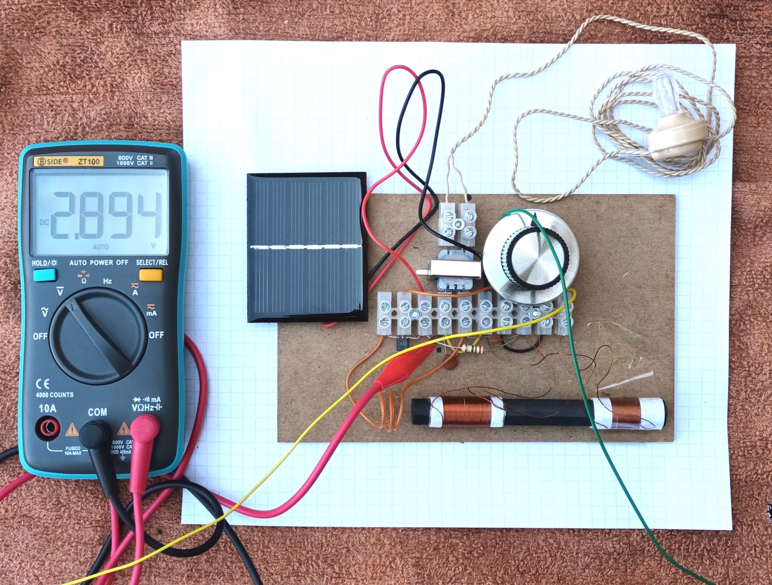
If you have a small solar battery that is specified to provide
anything up to 3 Volts, you can use it to power the radio. In the
pictures below, my miniature solar panel is rated at 3 Volts, 0.3
Watts, 100mA maximum. This assumes that you're in the Sahara
desert at noon, but it provides more than enough power for this
radio indoors in bright office conditions. The sky was quite
overcast at the time that the picture was taken, and you can see
the 2.894 V output from the miniature panel reading on the
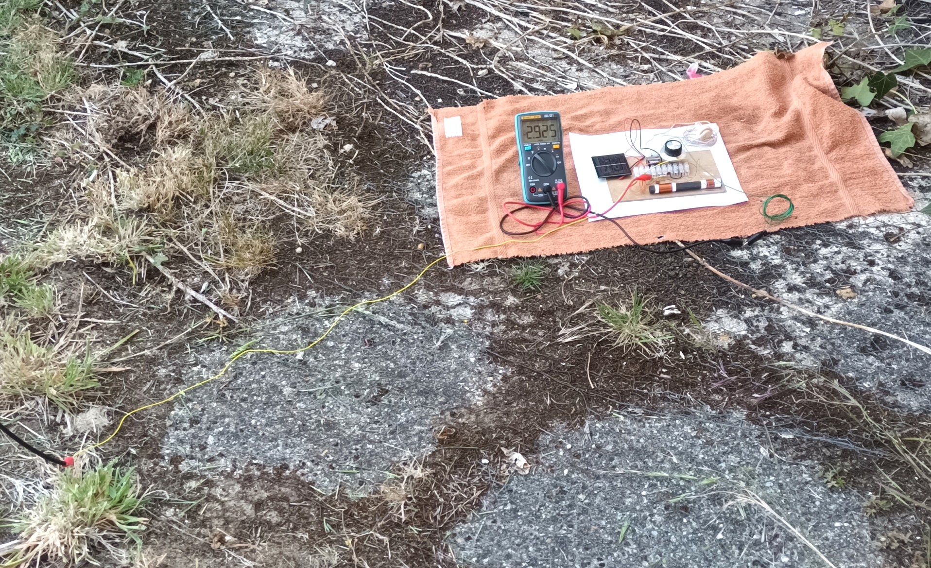
meter. For an aerial and earth in these pictures, I'm
connected to some chicken wire on the ground, and 3 metres of
vertical wire attached to a washing line, which is more than
adequate. You can sometimes find old solar powered garden lights
where the plastic covering the photovoltaic cells has gone cloudy,
remove the sun damaged plastic, and use that instead of buying
something new.
Easy Peasy,
Lemon Squeezey
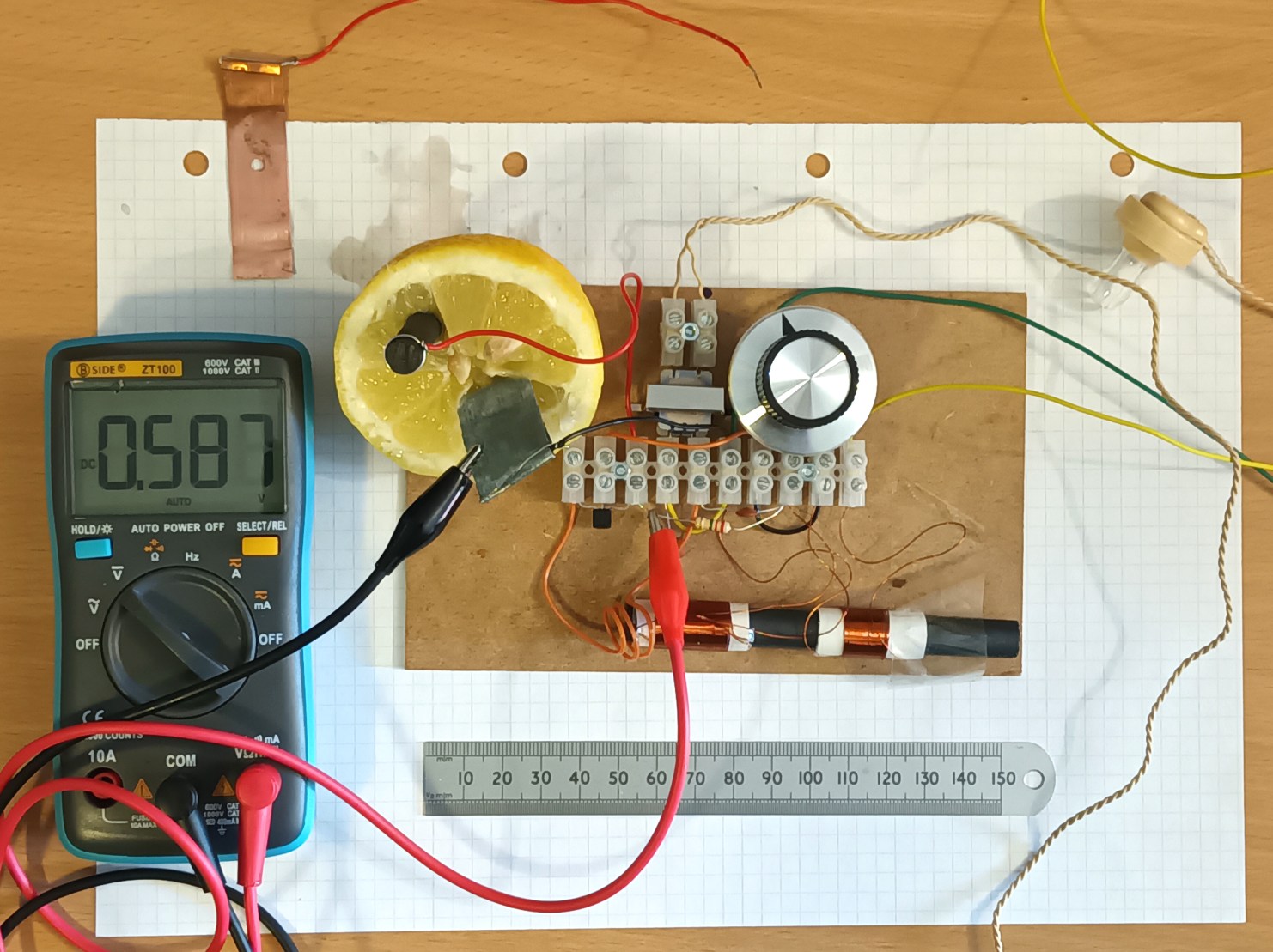
...as Sooty used to say. Or, "Lemon, Lemon, Difficult
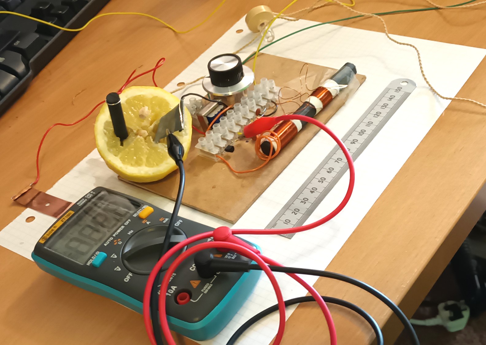
Lemon," as someone else said. Yes, you can use a lemon for a
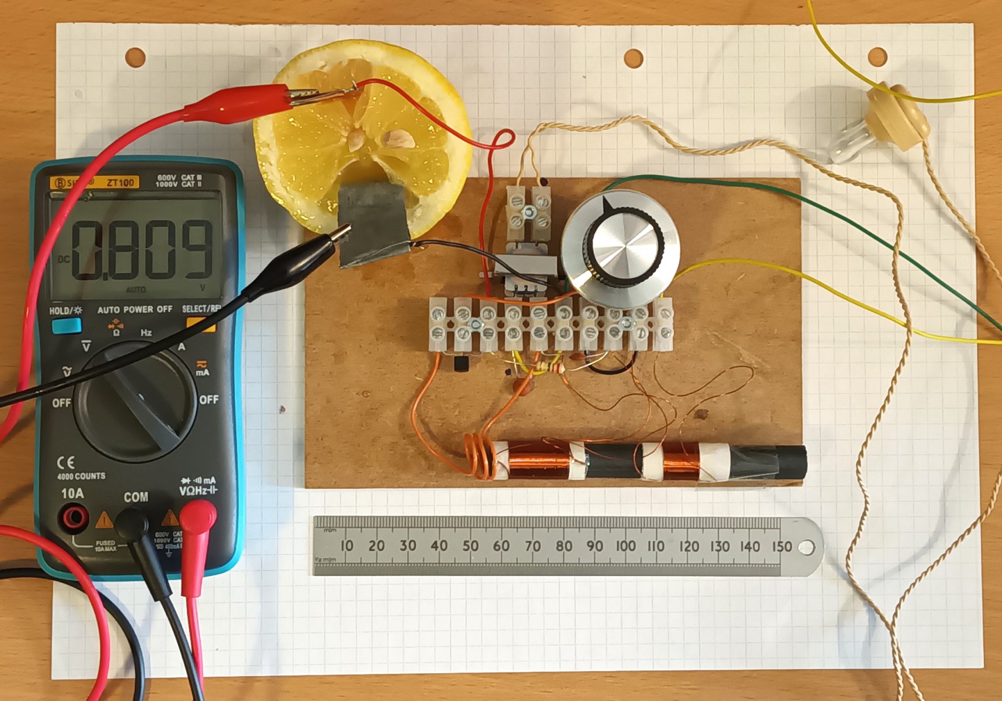
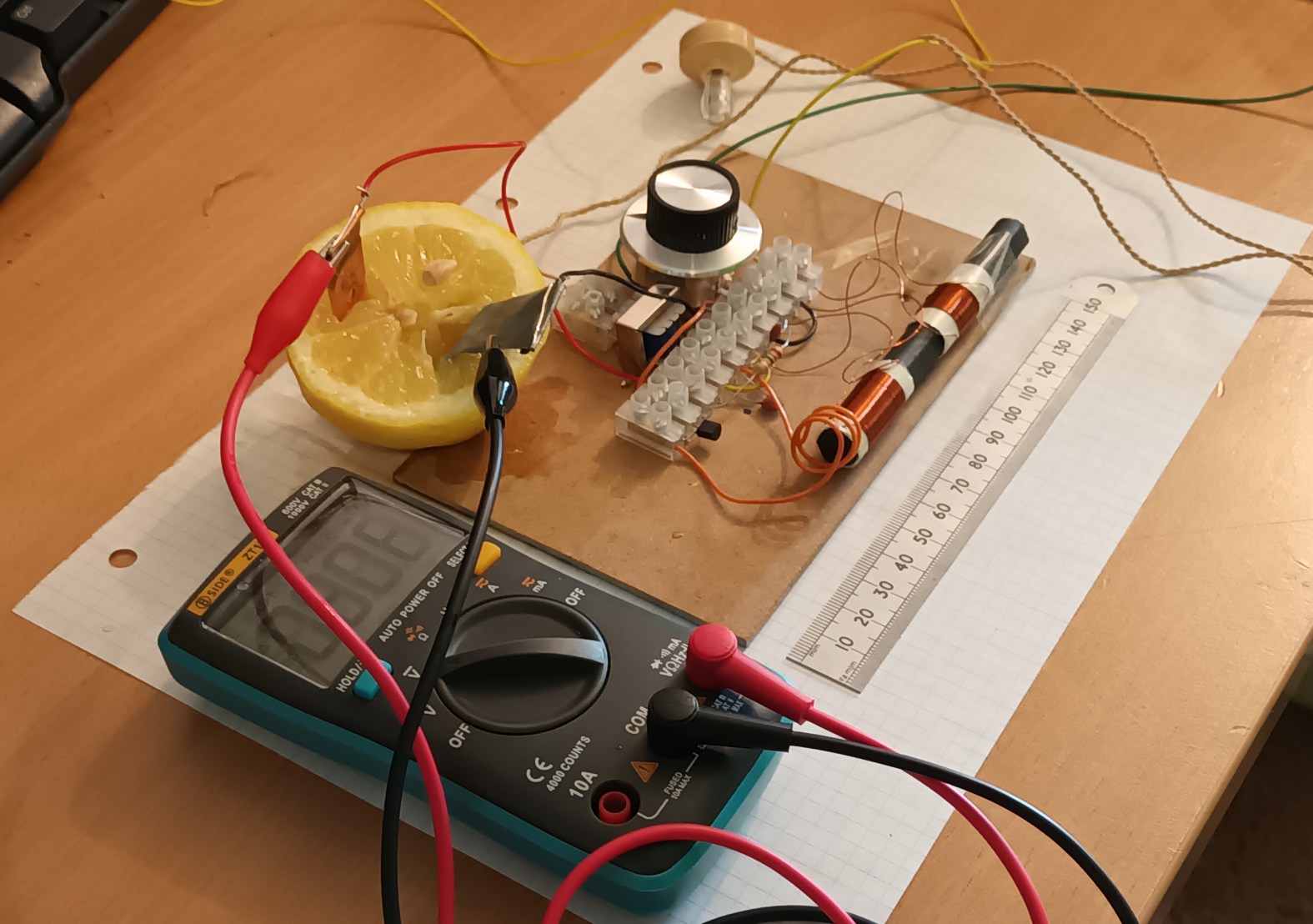
battery. You will, however, need a piece of copper or a
carbon rod, and a piece of zinc. Copper foil can be found
securing the output transistors to the chassis in old radios, or a
small piece of copper pipe. I'm not going to say where I got
my piece of zinc or carbon rod from, because it's not a safe
approach in modern times. (Let's just say, the 1960's Ladybird
book, "Magnets, Bulbs, and Batteries," will not be found in your
local library without a dire safety warning posted inside the
front cover) You can always get some online, or ask a
friendly science teacher. The acid in the lemon provides an
electrolyte. It's the difference in the chemical reactivity of the
metals that is really providing the power, as the zinc plate
slowly dissolves. Don't eat the lemon afterwards.
Carbon Rod
and Zinc Plate Lemon Battery Operation at 0.6V
Copper Plate
and Zinc Plate Lemon Battery Radio Operation At 0.8V
The Potato
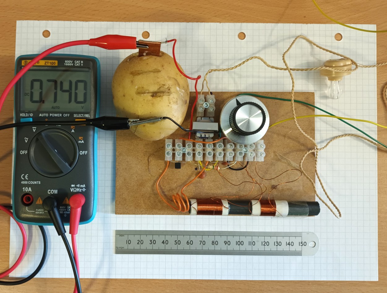
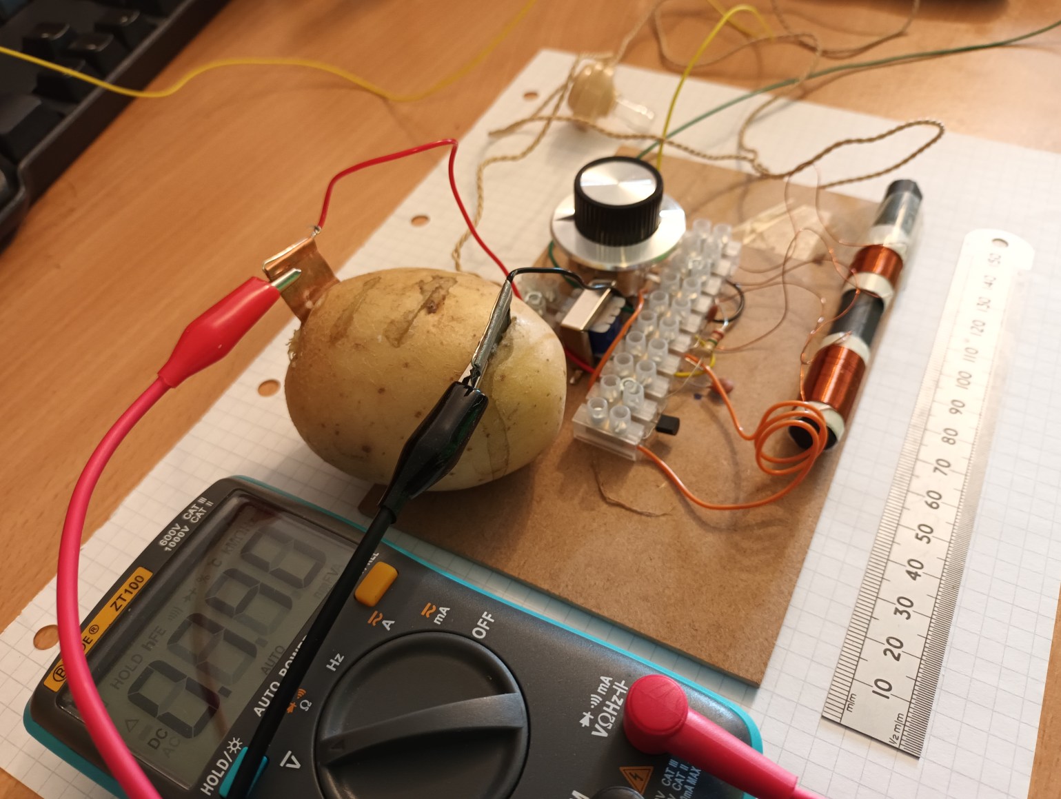
Programme 0.7V Operation
"Ah Helga, the
foolish imperialist Western
burgeoise use their fancy imported lemons, where we clever Soviets
can use a mere potato!"
'Yes, Boris. A potato is clearly a far superior option.'
Yes, you can use a potato. It's cheaper and you get less juice
going everywhere. Don't eat the potato afterwards. I promise that
this is the last of the, "fruit and veg" batteries.
Alessandro
Volta's Voltaic Pile Operating at 0.75 Volts
For historic purposes, you might want to try the original battery
invention from 1800. You could even try stacking more copper and
zinc plates to get up to 1.5V or more. I used salt water, kitchen
roll tissue for the separator, and just one copper and zinc
plate. Strictly speaking, that's a single cell. If you
stacked two, that would be a battery of two cells. Alessandro
Volta proved that you could generate electricity from metals, and
disproved the then ongoing debate about whether it was generated
from animal electricity with the whole, "twitching frog's legs by
poking them with a fork on a metal plate," thing.
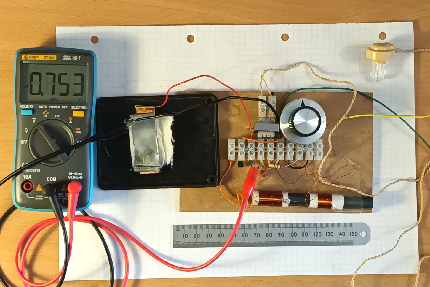
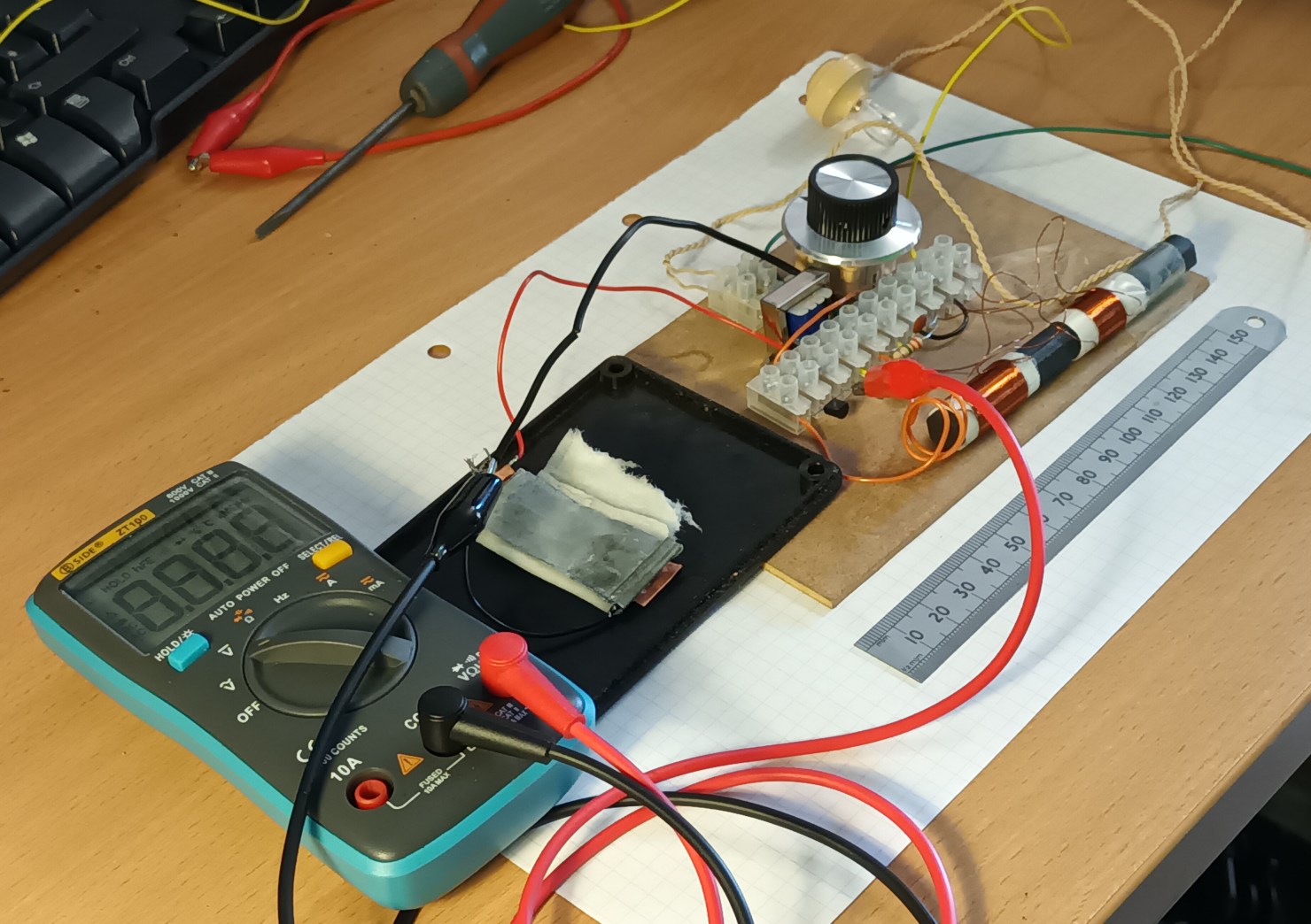
The alternative batteries are a bit of fun, and are great for
science lessons about electro-chemistry. In practice, buy a AA
battery for 20pee and use the battery holder provided. The "fruit
and veg" batteries do, however, show how this active diode type of
design works well down to ridiculously low voltages.
Aerials
(Antennas) And Earth Connections
I can make this radio work in most locations by connecting the
earth wire to a central heating radiator and just gripping the
aerial wire with my hand. Can you make it work with no aerial and
earth wire at all? Sometimes yes, just about. At my house
there are telephone wires radiating out like an umbrella from a
central pole in the middle of the street. It forms a shield
against MW radio signals. Solar panels on the house don't help the
aerial wire in the attic work much, either. If you're in a better
location and you want to try working with just the ferrite rod as
the aerial, remove the aerial coupling coil L1 pins 1 and 2 from
the ferrite rod completely. This worked for me in a location in
Todmorden, Lancashire, which is a long way from the Brookman's
Park transmitter. You could have greater success in the USA if you
still have a high power AM broadcaster within 50 miles, or a small
station nearby.
Longwave (LW) And Shortwave (SW) Operation
LW
Longwave radio broadcasting is on its last legs. For shame! To
receive it on this radio you would need a main resonant coil that
is 200 turns, an amount of wire that I don't provide in the kit,
and surprisingly intuitively, a long aerial for long waves. BBC
Radio 4 198 kHz still soldiers-on from Droitwich at 500 kW, while
the remaining Economy 7 electricity meters in the UK are turned
off from the phase modulated teleswitching signal which that
transmitter provides, and are turned into smart meters. If
you live in Algeria, however, a French language service Chaine 3
from Tiapazia operates on a full height quarter wavelength
monopole aerial on 252 kHz. Such extraordinary transmitting
effort can not go un-noted. I can receive it in Southampton, UK,
during the daytime as a routine domestic experience with a
cool cardboard loop resonant aerial antenna, though I have
yet to make the single transistor modification work to hear
it.
SW
If you completely remove the main coil from the ferrite rod, it
will resonate at SW frequencies. China are big on high power SW
broadcasting at the moment, not least because the West have
vacated some of their old frequencies. Problem. The ferrite rod is
not only used to make the inductance change frequency, it coupled
the signals together. So now, taking out the ferrite rod has made
the reception frequency higher, but the aerial and earth coil is
lost in space. Either wrap the aerial and earth wires connected
together directly around the main coil, or connect them straight
to the top of the resonant tank to hear various goings-on at 2MHz
and above.
That's it for now. This is a new page, so please report any errors
or confusion to me at the email address below.
How
It Works For The Electronics Engineers.
The link above provides some more detail and oscilloscope
pictures, mostly aimed at electronics engineers.
Navigate Up
My email address checked daily is: 
Recent edit history
20-NOV-2025: nocache directive added


