The
HJW
Electronics Choccy Block Crystal Set Radio Kit CBCSRK-1T


I've sold lots of these since 2011, and people are having plenty
of success with them. If you're thinking of buying one of the
commercial plastic sets without an aerial coupling coil, output
transformer, and with an untested earphone, please consider this
one instead. I can confirm that it is much better, and you won't
risk the 40% chance of getting a dud earphone that are the
current odds. (See The
Problem
With Crystal Earphones)
A
complete kit of all the electronic parts shown is available,
and the details of how to buy are shown below.
Sales
Outlets:
The kit is
also available on various online marketplaces, where
overseas shipping options are available to some
countries. Please see Usefulcomponents
/ HJW Electronics Online Marketplaces
Introduction
This is a small crystal
radio which can be constructed without soldering using 3A
terminal strip or "Choccy Block." It's best to read
right through the page first before starting out.
How To Build The Radio
Here is the electronic schematic
diagram. If you're familiar with electronics this will be
helpful. If not, you can just look at the pictures to
build the kit. In addition to the parts provided in the
picture you will need a screwdriver for the terminal block,
some pliers, some wire cutters and some form of wire stripper.
To make the paper tubes for the coils you will need some
paper, glue, scissors and sticky tape.
Schematic Diagram - Click To
Enlarge

Link
to PDF Schematic Diagram Of Choccy Block Crystal Set Radio
Bill Of Materials (BOM):
Qty Refs Type
Value
1
3
Amp terminal strip
1
LT44
transformer
1 VC1A variable
capacitor
210PF total
2
M2.5
4mm screws
3
M2.5
20mm screws
3
M2.5
nuts
5
M2.5
washers
1 D1 silicon
Schottky diode
BAT48
1 C1 ceramic
disc capacitor
470PF
1 Y1 ceramic
/ crystal earpiece
1 30SWG
/ 0.315mm enamelled copper wire 4m
1 1m
yellow aerial connection wire
1
1m
green earth connection wire
1 1
yellow insulated crocodile clip
1 1 green insulated crocodile clip
1 control
knob for short shaft
1 100mm
long, 9.5mm diameter ferrite rod
1
300mm
single core red hookup wire
1 300mm
single core black hookup wire
1 R1 carbon
film resistor 0.5W
2M2
2 C2,C3 ceramic
disc capacitor
100NF
1 Q1 NPN
small signal transistor
BC549C
1 J1 Single
AA battery holder
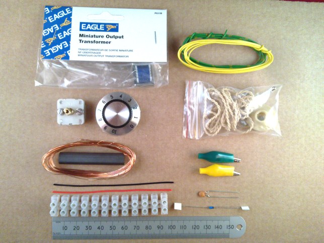
The
underlined items in the parts list above are links to more
detailed descriptions. You don't need to look at, or
understand the contents if you just want to make the
kit. The last four items in the BOM are included in the
kit, but they are a 2025 addition. You might decide to scroll
down to the bottom of the page to find out how they can be
used.
General Connections
Link to Large Photo of Choccy
Block Crystal Radio Wiring

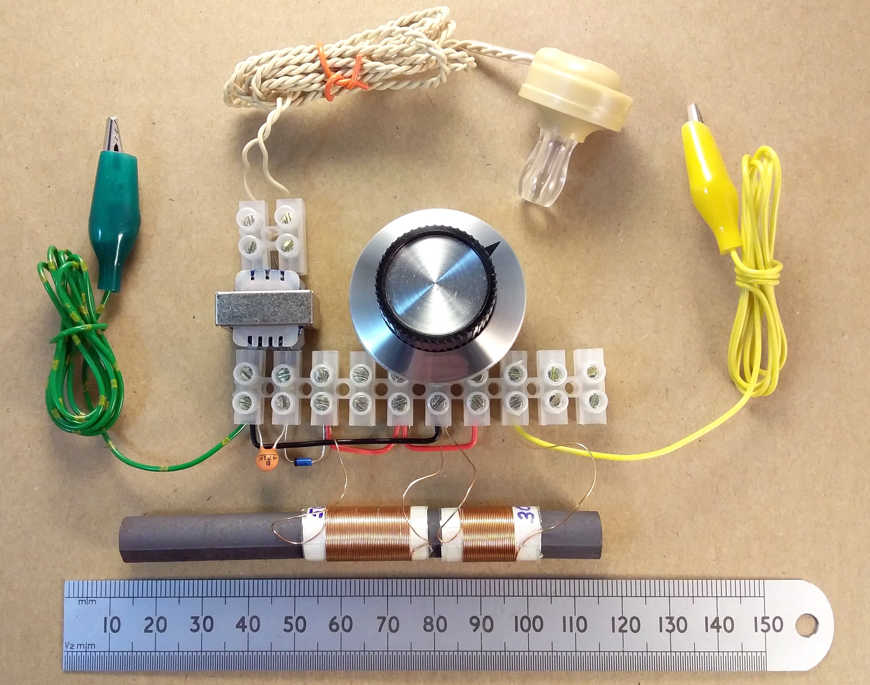
In the photo above you can see each component and where it is
connected quite easily, using the large wiring picture if
needed. You need to cut a group of two terminals from
one end of the block for the connections to the
earpiece. The red and black link wires, the aerial and
earth wires, and the crystal earpiece wires need to be
stripped of plastic insulation where they connect into the
terminal block. The coil wire ends need to have the
enamel insulation scraped off where they connect in. The
LT44 transformer should be connected so that the outer two
wires of the end with three wires are connected to the
earpiece wires. You can leave the middle wire
disconnected. The transformer is best butted right up against
the terminal strip which gives it a little bit of support to
stop the wires bending. The same applies to the variable
capacitor.
The Variable Capacitor
Connections
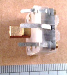
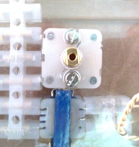
Looking at the variable capacitor
from the bottom side, the side without the control shaft, you
will see two trimmer screws and the three strip
connections. The two trimmer screws add extra fixed
capacitance to the variable elements. They should be
adjusted as shown in the third photograph for minimum extra
capacitance. This is the position where the
semi-circular moving plates attached to the screws are clear
of the lower metal plates.


The middle strip is the common ground for the two capacitors
and the outer strips are the remaining connections. The
variable capacitor is actually two capacitors which are
connected together in the terminal strip circuit. As
supplied, the connection strips exit at the side of the top
face of the capacitor. To fit it into the terminal strip
you need to remove the transparent plastic case of the
variable capacitor, and unfold the strips so that they go out
of the holes in the bottom face, as shown in the picture
sequence.


Making the Coils
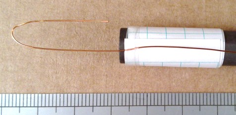
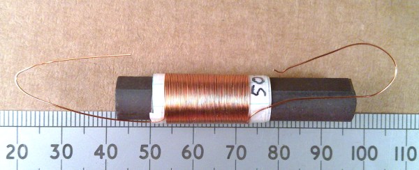
To wind the coils you need the
wire supplied, some sellotape, scissors, ordinary paper and
some glue. The process in shown in the pictures. You first
need to make two paper tubes by cutting a piece of paper 25mm
wide and about 100mm long and another about 20mm wide by 100mm
long. The tubes are formed by applying glue to two thirds of
the length of the paper and wrapping it loosely around the
ferrite rod. The tubes need to be able to slide up and
down on the rod, so don't wrap it too tightly. It's best to
leave the glue to dry before winding the wire on so that the
tube doesn't crush and bind on the rod. The wire is secured at
one end of the paper former with a thin strip of tape and then
for the larger main coil, wind 50 turns onto the tube. The
aerial coupling coil requires just 30 turns. It is better to
turn the tube rather than winding the wire around by hand,
because winding it around puts a twist in the wire. Again, you
need to wind the turns just tightly enough to stay in place so
that the coil and tube can still move on the rod afterwards.
At the end of each coil, another thin strip of tape holds the
far end of the wire in place. If you lose exact count of the
number of turns don't worry. It need only be approximate.
Update: The ferrite rod provided is now 100mm long, so
it's a bit easier to handle and you can make the paper tubes a
bit wider. You still want to be able to slide the antenna coil
close up to the tuning coil though.


Connecting to the Crocodile
Clips
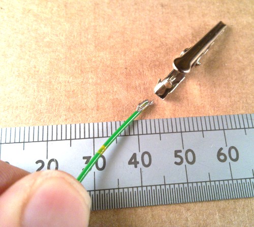
The crocodile clips are much more
convenient for connecting to aerials and earth connections
than bare wires. You need to strip the ends of the yellow and
green wires first, then remove the insulating boot from the
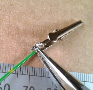
clips as shown. The metal flaps on the ends of the clips can
then be crushed down on the folded-back stripped wire ends to
make a firm connection before putting the boot back on from
the other end of the wire. To remove and replace the
insulating boot, hold the jaws open by clipping them onto some
small object.

Finishing Off
It is worth checking that all of the wires are trapped
under each screw correctly and that none of them will pull
out. When everything
is wired as in the main picture, the control knob can be
fitted to the shaft of the variable capacitor and you are
ready to test.
Testing and Operation
Connect the green earth wire to
your earth connection and the yellow aerial wire to your
aerial. With the coils in about the position shown, turn
the tuning knob until a station is heard. You may find that
you can increase the loudness of a particular station a bit by
moving the coils around on the ferrite rod, but the adjustment
is not critical. There's very little to go wrong, so
troubleshooting should be confined to checking that the
connections are made as shown. That concludes the building
instructions and should get you going. Once it's working you
can fix the terminal strips down to a wooden board by
carefully banging in nails down through the holes or using the
M2.5 screws provided. If you decide to fix the variable
capacitor to a front panel, only use the very short 4mm screws
provided. These are guaranteed short enough not to foul the
insides of the capacitor.
If you want to get on and build it, that's all you need to
know but there's more information below which might be useful
and some technical discussion.
More Information
Aerials and Earths
I have successfully used this to
pick up the main MW station in the UK just by connecting to a
central heating radiator for the earth and to the outer casing
of a television antenna cable, disconnected from the TV, for
the aerial. This is not ideal because the TV cable is nailed
to the house which both blocks and drains away a lot of the MW
radio signal. It is much better if you can erect a long wire
high up in a garden and there are many places online which
will show you how to do that, taking the usual precautions
against lightning strikes and going near to power
cables. Not everyone has a garden though, and you don't
want the TV aerial being disconnected on a regular basis, so
there are other interesting ways to get an aerial and earth.
Farm and Other Fences
While out walking I wondered if
there were any useful MW signals being picked up on farm
fences. They are not good aerials for a number of reasons, but
they can be quite long which can make up for that. You need to
connect the earth clip to the lowest wire and the aerial clip
to the highest wire. They will always be a bit corroded so you
have to wiggle the clips to get a good connection. If
you find a fence in good condition, outside of a deep valley
which has dry posts and isn't covered in wet bushes, you will
almost always get reception of one or more station. Station
pickup depends on the direction of the fence as well, so it's
worth trying a few if you are out walking.
Some fences are electrified and it will be pretty clear which
those are, those being a single wire with insulated posts.
Obviously, I have to say it: Don't use those.
Update September 2011: If
you get a high-ish spot and a decent dry fence this can work
even better than I expected. I walked up Clee Hill in
Shropshire recently and attached the set to an ordinary
fence with the ground wire clipped to the standard square
mesh below and the barbed wire on top. I wasn't expecting
much because the mesh and wire sections have little
separation, only a few inches. Signals from Absolute radio,
Five Live and another station were good and loud. I needed
to move the aerial coupling coil away from the main coil on
the rod to help separate the stations. The air traffic radar
station in the background is coincidental.
Update October 2011: The New
Forest campsite at Holmsley is neither particular high, nor is
the fence all that uncluttered; Still I picked up three
stations from there and found that it was best using either
myself holding the green clip for the ground or the very
bottom fence wire which was partially buried.

Other Structures
If you see any two metal
structures which are not obviously connected together you can
see if there is reception available from them. For example at
various times in the past, crystal radios have been used in
prisons connected to a water pipes for an earth and a bed
frame for an aerial. Always stay away from using the
electrical mains earth and avoid connecting to household
appliances.
Boxing it Up
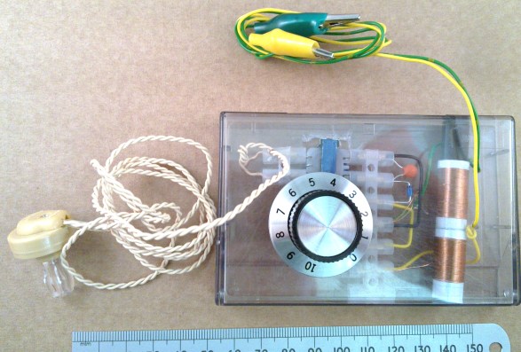
If you want to carry this around
on walks, it's a bit inconvenient in the basic form which was
intended to be the easiest way to build it up. If you want to
put it in a small box, the first thing to do is to change the
variable capacitor connection strips back around so that they
once more exit at the same side as the shaft. You can then fit
the variable capacitor into the terminal strip upside down so
that the shaft faces downwards, or outwards from your box, and
the terminal strip and transformer will all be flush with the
same surface. I've shown an example below where I have used an
old cassette case. This isn't very good because the
transformer is too big so you have to cut a hole for it in the
back. It doesn't matter which terminal strip connection along
the block each circuit node connects into, so you can shuffle
the parts along towards the left to save space, and cut off
the unused terminals. The tuning knob is specially selected as
one which works well with this tuning capacitor: The grub
screw is quite near to the bottom of the knob and it has a recess underneath which
clears the mounting screws. This allows it to fit well on the
short tuning shaft.

Soldering
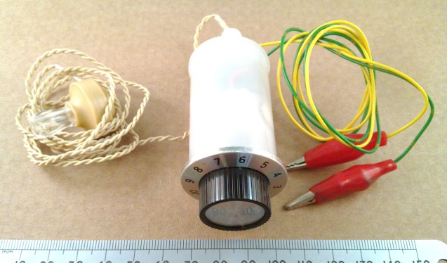
If you're happy soldering the
wires directly together it is possible to squeeze things up
even further. If you shorten the ferrite rod and wind
the coils in a small pile you can just about fit the whole
thing into an old 35mm film canister. The tuning knob sits
neatly at one end. Something a bit like this was used in
the Maze prison in the early 1980s. If you want to shorten the
ferrite rod to fit it in a box, first use a hacksaw to cut a
shallow notch in it. Then wrap the rod in a tea towel and snap
it into two pieces at the notch by hand.
Further
Technical Discussion
Circuit
Operation -
Earpieces
Anyone who's played with crystal sets a bit will see that
everything in the circuit is pretty standard. There are some
small points to note. The beige coloured ceramic / crystal
earpieces are quite sensitive and in circuit model terms
appear much like a 26nF capacitor in series with some lossy
resistance. 26nF is about 6K Ohms impedance at 1kHz. The
LT44 is used in reverse to provide a higher impedance audio
match to the top of the tuning coil via the diode. Looking
into the diode side of the transformer, the
impedance actually increases when the the earpiece is
connected due to a fortunate broad resonance with the earpiece
and transformer leakage inductances. The result is audio which
is a bit restricted on bandwidth but which has a fairly good
match and efficiency. Some of the ceramic earpieces in the supply chain are
very poor at the moment and I recently sent back 67 out of an
order of 100 as completely dead on arrival. The ones supplied
with the kit are 100% tested.
Diodes
You can use a 1965 Mullard OA81 or OA91 germanium point
contact diode if you really want to. In this circuit I've
found that the modern low Vf silicon Schottkys work as well as
the best germanium diode out of the junk box, and a lot better
than a poor one of which there were plenty.
Coils
You can go to great lengths to improve the Q of crystal radio
coils with modest results. If you wanted to eek a bit more out
of this one, separating the turns on the tuning coil by one
wire separation might help a bit if you are really going for
it.
FAQs
Q: Can I use some different headphones?
A: Generally the 32 Ohm headphones that come with
portable audio equipment won't work in this circuit. The
ceramic earpiece and transformer combination are intended to
get the best loudness from weak signals. If you have some
special high impedance radio headphones, those might work.
Q: I've read that piezo earphones like those used here
have more than 1 Million Ohms impedance. Surely that is high
enough to connect directly without the transformer?
A: This is a common misconception. These ceramic element
earphones have more than 1 Meg Ohm resistance at D.C. as you would measure with
a multimeter, but they have quite a high capacitance. At
audio sound frequencies like 1kHz, that capacitance has an
impedance of about 6K Ohms. 6K is still quite high but this
makes for a very poor radio if you connect the diode to the
top of the tuning coil and the other end of the diode direct
to the earpiece, as it loads the tuned circuit too heavily
giving very sloppy tuning and is also a poor power match
giving low sound level. Unfortunately you see this statement
and circuit configuration all too often.
Q: What does the ferrite rod do in this crystal set
radio?
A: That's a good question, worthy of a separate page
with an
explanation of using a ferrite rod in a crystal set radio.
Q: Isn't AM radio dead in the UK?
A: As of early 2025, not quite. Absolute Radio dropped off-air
before the end of their license agreement under an Ofcom
cloud, some time ago. My local Classic Gold at Fareham went
off last year. There's still some AM fun to be had, especially
if you're near one of the remaining music stations like
Caroline out at Orford Ness in Kent, Lyca Radio at Brookmans
Park in Hertfordshire for some Bangra, and BBC Five Live and
talkSPORT also at Brookmans park. BBC Radio Wales and Scotland
still put out a strong signal too, and there is some Punjabi
weirdness on 558 kHz, where you may hear religious music for
hours at a time completely free from advertisements. Now
that's commitment!
Q: Does it matter which direction you wind the two coils
in?
A: No. In this instance, it makes no difference.
Q: Does it matter which way round the diode goes?
A: No. It can go either way round in this instance.
Q: Can I wind the coils on a metal sleeve so that I can
slide them up and down more easily?
A: No. The metal will form a shorted turn and completely
eliminate any signal. You could use some small bore plastic
pipe or some cut-up lemonade bottle, though. Watch it; Cut-up
plastic lemonade bottle can be sharp.
Q: The knob shown in some of the pictures has 0 to 10
markings, and the one delivered has a pointer triangle.
A: The pointer type is more appropriate. The variable
capacitor only rotates through 180 degrees and the numbers
cover 300. I'll change the pictures on a major update.
More
on Crystal Earpiece History
"When I were a lad..." OK,
but bear with me on this one. In the distant past I had
two or three of these items. One came with a Japanese
"Gakken 150 in 1 electronics kit" with the spring terminals,
and another one or two came a local shop in Blackburn. I've
discussed elsewhere that one of these worked spectacularly
well, and others less so, probably due to the 'good' one
having some leakage resistance. That would make the standard
poor crystal radio circuit without a bleed resistor across the
earpiece or a transformer work OK. But at some stage, one of
them finally broke and I thought that I would take it apart to
see how it worked. What was inside?
The two wires under the screw-down cover go to terminals
embedded in the plastic much like the current items. On the
other side there were two conductors that converged at an
apex, where there was a small lump of something which I assume
was a piezo crystal of some sort. This was quite small, a
maximum of 3mm diameter. This poked through and was glued
through a very fine, easily broken aluminium diaphragm. You
could see this glued part from the other side when you removed
the earpiece tube. This contrasts with the current design
which has a flat piezo element of maybe 15mm diameter on a
stiffer diaphragm, much like you'd see in the back of a
digital watch or standard piezo sounder. The question is, were
these old earpieces genuinely higher impedance, i.e. lower
capacitance due to having this smaller area crystal, and with
the lighter diaphragm also possibly higher efficiency?
It might explain why so many current crystal set designs just
assume you can connect these similar-looking modern earphones
directly.
Astute readers of the
instructions so far may have noted that as of JUL-2025,
there are two unused capacitors, a resistor, a transistor,
and a AA battery holder included in the standard crystal
set kit as an added extra bonus. Please click on the link
above to discover more, especially if you're in a poor
reception area, or can't get much aerial wire aloft. It's
amazing what you can do with one transistor and a single
AA battery, or even a lemon.
Should you have any problems or questions, my
main email address is shown below. This address has been the
same since 1997, and unless I'm on holiday, it is checked
daily including the spam folder:
Navigate
Up
© Henry J. Walmsley 2010-2026.
Recent Edit History
22-NOV-2025: self
canonicalised, all links changed to
direct, some html checks.
02-JAN-2026: email link went weird,
corrected, some formatting


